Plate Heat Exchangers: Principles, LMTD and Heat-Transfer Area
Why plate exchangers are more compact and efficient, and how to estimate the required area with the LMTD method.
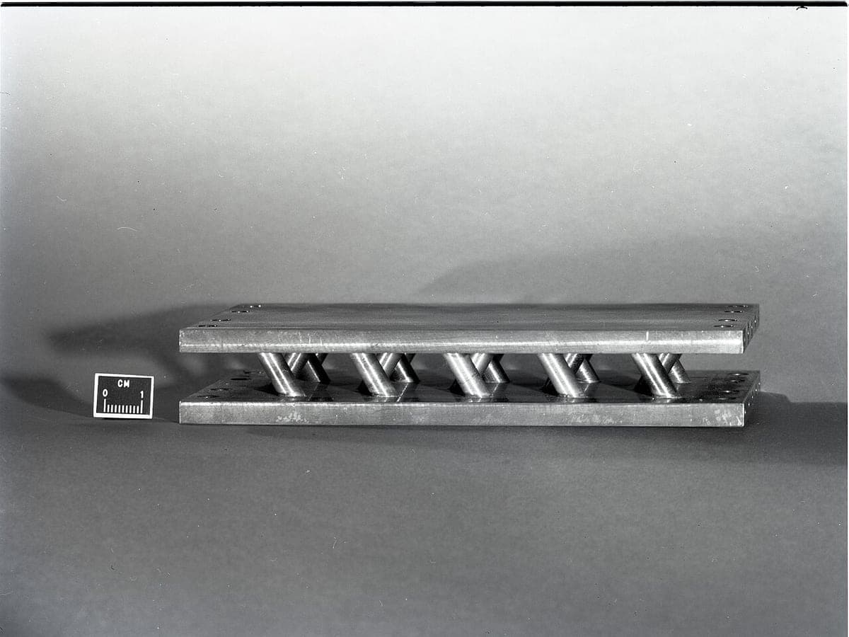
Photo: National Aeronautics and Space Administration. John H. Gl… · Public domain · Image credits
How it works
A plate exchanger is built from thin corrugated plates that route hot and cold fluids through alternating channels. The corrugations induce turbulence and raise the heat-transfer coefficient several times above a shell-and-tube unit.
The basic design equation
Q = U · A · LMTD
LMTD = (ΔT₁ − ΔT₂) / ln(ΔT₁ / ΔT₂)
Q is heat duty, U the overall heat-transfer coefficient, A the area and LMTD the log-mean temperature difference. When both end differences are close, LMTD ≈ arithmetic mean.
| Arrangement | ΔT₁ (°C) | ΔT₂ (°C) | LMTD (°C) |
|---|---|---|---|
| Counter-flow | 28 | 28 | 28 |
| Parallel-flow | 70 | 3.4 | 22 |
Design example
To transfer 500 kW with an LMTD of 12 K and U = 4000 W/m²K: A = 500000 / (4000 × 12) ≈ 10.4 m². With a 20 % fouling margin, about 12.5 m² is selected.
Comparison with shell-and-tube
| Feature | Gasketed plate | Shell-and-tube |
|---|---|---|
| U (W/m²K, water-water) | 3000 – 7500 | 800 – 1500 |
| Minimum approach | 1 – 2 K | 5 – 10 K |
| Footprint and weight | 20–30 % of shell-and-tube | Baseline |
| Maximum pressure | ≈ 25 – 40 bar | > 100 bar |
| Cleaning and expansion | Easy; add plates | More difficult |
Fouling
Hard water and high wall temperature accelerate fouling. For city water a fouling factor of 0.00002–0.00005 m²K/W is typically assumed.
Related articles
Steam Trap Selection Guide: Types, Principles and Common Mistakes
Why one failed trap can waste thousands of dollars of steam a year, and how to choose the right trap.
2 min read
Control Valve Sizing: Flow Coefficients Cv and Kv in Practice
From the basic formula to selecting size and trim characteristic, with a worked example and a Kvs table.
2 min read
PID Controller Tuning: Fundamentals, Methods and Step Response
The effect of each parameter, Ziegler–Nichols and lambda tuning, with a simulated first-order-plus-dead-time process.
1 min read