The 4–20 mA Current Loop: Principles, Wiring and Troubleshooting
Why it has been the industrial signal standard for over half a century, and how to design it properly.
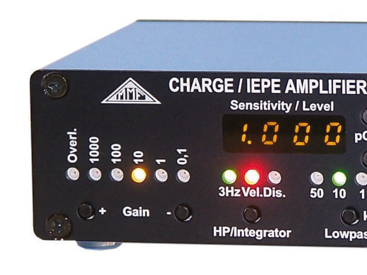
Photo: JanBurg · CC BY-SA 4.0 · Image credits
Why current, not voltage?
In a series loop the current is identical everywhere, so voltage drop on a long cable or contact resistance does not change the signal. That is why current transmission is far more robust than voltage over hundreds of metres in noisy plants.
Why does it start at 4 mA? (Live zero)
Zero percent of the process is represented by 4 mA, not 0 mA. A 0 mA signal then clearly means a broken wire or failure, and a 2-wire transmitter can power itself from the 4 mA.
I (mA) = 4 + 16 × (PV − LRV) / (URV − LRV)
Loop burden
The transmitter needs a minimum voltage (typically 12 V). The rest of the supply may drop across cable resistance and the PLC input:
R_max = (V_supply − V_min) / 0.020 A
Comparison with other standards
| Standard | Noise immunity | Cable length | Fault detection | Typical use |
|---|---|---|---|---|
| 4–20 mA | Excellent | Up to kilometres | Yes (live zero) | Transmitters, actuators |
| 0–10 V | Medium | Tens of metres | No | Panels, buildings |
| 1–5 V | Medium | Tens of metres | Yes | Legacy DCS |
| HART | Excellent | As 4–20 mA | Yes + diagnostics | Smart transmitters |
Quick troubleshooting
- 0 mA: broken wire, blown fuse or no supply.
- Below 3.6 mA: the transmitter is signalling a fault (low alarm).
- Above 21 mA: sensor failure or short (high alarm).
- Fluctuation: double earthing or unshielded cable beside power cables.
Tip
Ground the cable shield at one end only (panel side) to avoid creating a ground loop.
Related articles

Steam Trap Selection Guide: Types, Principles and Common Mistakes
Why one failed trap can waste thousands of dollars of steam a year, and how to choose the right trap.
2 min read
Control Valve Sizing: Flow Coefficients Cv and Kv in Practice
From the basic formula to selecting size and trim characteristic, with a worked example and a Kvs table.
2 min read
PID Controller Tuning: Fundamentals, Methods and Step Response
The effect of each parameter, Ziegler–Nichols and lambda tuning, with a simulated first-order-plus-dead-time process.
1 min read